
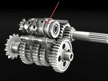
In the pursuit of shaving fractions of a second off lap times, the automotive industry automated manual transmissions to make gear changes faster, more synchronized, and more efficient. This advancement gave rise to quickshift and paddle shift systems in motorsport, technologies that transformed the way drivers shift gears in competition vehicles. The first Formula 1 car to feature this type of system was the Ferrari 640 in 1989. In the early days, only upshifts were possible; with the introduction of the electronic throttle, downshifts became viable as well.

Figure 1 – Sequential gearbox
Quickshift system
The quickshift system works from a load cell, which detects the compression or extension of the spring inside the gear lever. Depending on the system’s construction, compression will result in either an upshift or downshift signal.
In a manual transmission, the clutch must be engaged to disengage torque coming from the engine from the gearbox. In this system, however, torque reduction is achieved by having the ECU momentarily cut ignition, preventing combustion inside the engine. A large portion of the injected fuel burns off in the exhaust manifolds, due to the high temperature in that region, producing the characteristic popping sound of the cut.
The evolution of this system, enabled by a drive-by-wire throttle, made it possible to perform downshifts with synchronized gear speeds. In a manual transmission, all three pedals must be used simultaneously to achieve maximum braking performance during gear changes. With this electronics package, when the ECU detects a downshift is taking place, it opens the throttle, revving the engine up to the correct RPM for that speed in the lower gear. This allows the driver’s right foot to stay solely on the brake pedal, without needing to perform the movement known as “heel-and-toe,” resulting in less variation in brake pressure for amateur or semi-professional drivers.
During downshifts, the driver is responsible for ensuring the correct timing between gear changes, since there’s no safety interlock preventing an overrev (exceeding the engine’s maximum RPM limit). During acceleration, the RPM limit is enforced electronically by cutting ignition/injection or closing the throttle. However, when an overrev occurs during a downshift, the gearbox spins the engine beyond its allowed maximum. This can cause permanent engine damage due to valve float at excessive RPM. This happens when valve inertia becomes high enough that the spring can no longer close the valve at the correct moment. To prevent this, it’s common to use springs with a higher spring rate, titanium valves, or even replace the system with a pneumatic one. The vehicle manual should list overrev ranges along with their duration and/or event count and the corresponding maintenance intervals. In the image below, taken from the technical manual of the Porsche 911 GT3 Cup model 997.2, the engine must be rebuilt every 50 hours, provided no overrev has occurred. For overrevs in the 9,000 to 9,500 RPM range, the seconds spent in that range must be logged, and if it exceeds 6 seconds, the vehicle must be taken to the dyno for a functional check. If time spent between 9,500 and 10,000 RPM exceeds 2 seconds, the engine must be rebuilt immediately, as is the case if the engine exceeds 10,000 RPM even once.

Figure 2 – Porsche 911 GT3 Cup model 997.2 engine rebuild schedule based on overrev time and RPM
Paddle shift system
As electronic management advanced, it became possible to remove the gear lever entirely and introduce paddle shifters behind the steering wheel. This system consists of levers that trigger buttons behind the wheel. The mechanical construction principle of the gearbox doesn’t differ from the previous system, except for the gear engagement mechanism. In the quickshift system, the driver performs the physical movement to change gear; with paddle shifters, a hydraulic or pneumatic actuator is responsible for carrying out the movement in the gearbox. Since the actuator requires an electronic command to move, it became possible to build in conditional logic for the task. In the case of a downshift, the ECU instantly calculates the new RPM using the gear ratios. If the left paddle is pulled and the resulting RPM is below the engine’s RPM limit, the ECU allows the shift to happen. If the RPM would exceed the limit, no gear change occurs. Some systems allow the electronics to store the downshift request briefly and execute it as soon as it’s safe to do so. Other systems lack this memory function, and the driver must pull the paddle again at the correct moment to complete the downshift. All of this conditional logic brought greater safety to internal components, since an overrev becomes impossible.
The table below shows the gearbox shift conditions for the Porsche 911 GT3 Cup model 991.1, for both upshifting and downshifting. Besides the condition that prevents overrev, the other conditions involve pedal position, clutch engagement, RPM, speed, and pneumatic actuator pressure.

Figure 3 – Porsche 911 GT3 Cup model 991.1 gearbox shift conditions for upshifting and downshifting
Since the system is only ever subjected to the RPM ranges it’s designed for, manufacturers can reduce the transmission’s safety margin, making it lighter than its manual counterpart. This is one of the reasons Porsche moved from manual transmissions to the PDK (Porsche Doppelkupplungsgetriebe — Porsche dual-clutch) in the brand’s sportier models. The reduced weight improved the vehicle’s dynamic behavior. Recently, the German manufacturer brought back the manual configuration as an option, due to market demand for a more engaging driving experience.
Calibrating ignition cut, throttle opening, and the position sensor
All of this electronic management depends on fine calibration to extract maximum performance, meaning maximum speed and smoothness between gear changes.
As described above, the upshift strategy relies on cutting ignition, but the duration of the cut must be carefully sized. It typically falls between 35 and 80 ms. For the downshift blip, the throttle must open between 12 and 30% over a window of 70 to 200 ms. Of the two strategies, the downshift is more complex, since throttle opening and its duration are variable — the RPM increase needed depends on the target gear and the initial RPM at the start of the process. Each gear has its own transmission ratio, so the blip needed to downshift from sixth to fifth is smaller than from second to first, due to the smaller RPM delta at the same speed. For a downshift within the same gear pair, the initial RPM also affects the calculation, since the RPM delta scales linearly with the starting RPM. Downshifting at 3,000 RPM requires only a small amount of engine acceleration time, while at 6,000 RPM the RPM delta for the next gear is larger, requiring more engine acceleration time to properly synchronize the gears.
In the quickshift system, it’s important to calibrate the force required to trigger the system. A trigger with too little force will cause the shift procedure to start prematurely, and consequently end with ignition returning while gear engagement is still taking place. Too much force on the load cell, besides causing discomfort for the driver and occasionally failing to register a shift, will cause the ignition cut to start too late, which means the current gear’s gear pair disengages while torque is still being generated.
There’s also the calibration of Mask Time, which is the period during which the gearbox system remains inactive before it can register a new gear change. This logic exists to protect the transmission by preventing gear clash. A new gear engagement can only take place once the previous one has fully completed. On motorcycles, this physical limitation is easy to observe: with the motorcycle stationary and the engine off, shifting through a few gears eventually causes the shift pedal to stop moving due to gear clash, requiring the motorcycle to be moved to complete the shift.
The entire automated transmission assembly can only function correctly if the ECU can identify the gearbox position through a rotary potentiometer. Before the start of a race weekend, the engineer must confirm that the sensor’s voltage reading matches the specification table provided by the vehicle or transmission manufacturer. There’s a tolerance range for the measured value; if the reading falls outside the allowed window, the ECU won’t correctly identify the current gear.
In its technical manual, Porsche provides voltage data for the rotary potentiometer on the gear selector drum. Third gear is used as the calibration reference, which is why it’s shown with the tolerance window in the table below.
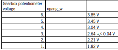
Figure 4 – Porsche 911 GT3 Cup model 991.1 gear selector drum rotary potentiometer voltages
In the image below, the gearbox position sensor was correctly calibrated. The reference value was set for the neutral position (neutral = gear 0). As the potentiometer voltage varies, the gear identified by the ECU varies accordingly. Sensor voltage is shown in yellow on the graph, while the gear reported by the ECU is shown in blue.

Figure 5 – Gearbox potentiometer voltage and ECU-indicated gear for the Ginetta G55 GT4 with correctly calibrated sensor
In this second image of the same transmission, the sensor was out of calibration. It showed a deviation of roughly 0.2V from the reference voltage, which meant that at the 34s mark a gear change was momentarily registered by the ECU before the dashboard briefly reverted to showing neutral. At 1:06, a downshift from second to first gear causes the ECU’s output signal to oscillate four times before the gear indication settles again at 1:20.

Figure 6 – Gearbox potentiometer voltage and ECU-indicated gear for the Ginetta G55 GT4 with incorrectly calibrated sensor
Some competition electronics units, such as Syvecs, MoTeC, and Bosch, support different maps (traction control, engine braking, pre-shift torque reduction) for each gear. An incorrect reading of the actual gear would result in the wrong map being applied, which reinforces the need for the engineer to ensure this sensor is functioning correctly.


